To quantify gas flow contribution to FAE and BTF’s, a CAVT must be performed in the unit, treating the unit as if it were a full scale physical model. Smaller scale physical or computer models can be used for situations where it may not be possible to do a CAVT. Check the Modeling Capabilities section for details.
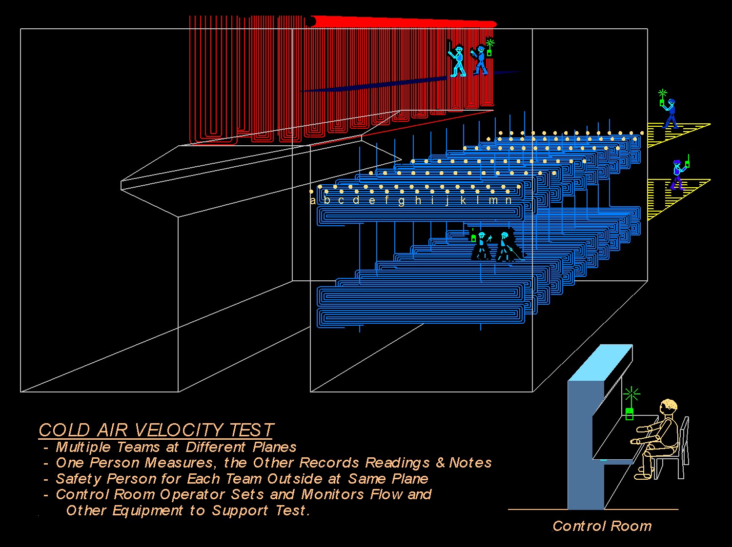
A test block of 8-hours is usually adequate, once fans are running. This block can be reduced to accommodate plant schedule by using multiple test teams. Teams would ideally use DRENNEN ENGINEERING and plant personnel plus a plant support person outside of the test cavity. Scaffolding may be required for vertical planes and all cavities should have light stringers installed.
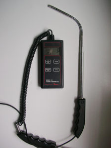
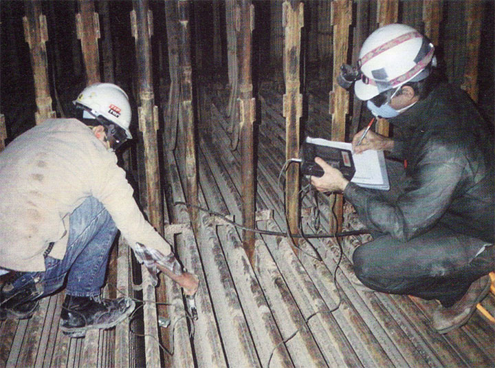
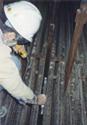
The CAVT is performed with FD & ID fans running at 80-100% normal flow (total flow down to 60% is permissible). Total flow and backpass temperature should be recorded during test via plant DAS. Measurement planes and points are identified on data sheets that each team has during the test. Test conduct, test planes and test procedure are review at the pre-test safety meeting. Velocities are measured with handheld anemometers by one team member and recorded by the other as shown in photos.
Before and during CAVT, team members visually inspect test areas and document with photographs and written notes. Significant items are pointed out to plant personnel attending.


Following the CAVT (time permitting), qualitative examination of the flow is done to capture features that are not revealed during the CAVT. This technique is described in the Flow Visualization section.