Unit assessment – Collection of fly ash erosion history and pressure part failure (BTF’s) summary, fuel and fly ash composition (chemical and crystalline fraction) and size distribution, cavity and pressure part design (dimensions, tube diameters, spacings, etc.), gas-side temperature profile, and unit operation (base load, peak, etc.).
Cold air velocity testing (CAVT) – At the beginning of a scheduled outage, unit unfired with fans running at 80% capacity, flow is measured in-situ at convective section inlets and outlets and in cavities where needed (80 – 100 points/plane). To minimize test block time, up to four teams can work simultaneously, each in a different section of the pass. To gain further insight into global and local flow patterns, flow visualization is done with smoke bombs in areas of interest. Photos and videos are made during inspection and testing to include with report.
Flow modification device type and placement are based on assessment and test data. Computer modeling is used to screen and then predict effectiveness of selected baffles and screens. These devices are selected to redistribute fly ash and reduce local flow rates in areas with serious FAE (achieving uniform flow is the goal of the program). CAD drawings with parts lists are made to document recommended flow modification system elements.
Following installation of recommended flow modifying elements, a second CAVT could be performed at the end of the outage to measure changes in gas flow. This helps identify system effectiveness and provides data for estimating change in FAE rates. If needed, modifications to installed elements would be identified and provided in an addendum to the final report. Modifications could be made by plant personnel at the next scheduled or unscheduled outage.

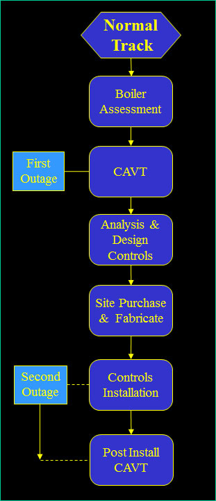
NORMAL TRACK - Program done in staged approach with CAVT and Assessment during one outage and installation of flow modifying elements during a subsequent outage. Second CAVT at end of outage or subsequent outage.
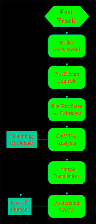
FAST TRACK - During one extended outage. Requires a predesign (by DRENNEN ENGINEERING, INC.) with materials purchase and fabrication by utility/contractor before outage.
CAVT is performed at beginning of outage. Installation proceeds during outage with second CAVT performed after installation of flow modifying elements. Deficiencies can be identified and remediation measures recommended. Changes can be performed before unit restart or at a subsequent outage.

At the initiation of an FAE control program, detailed information about your unit would be requested. The next step would be a site visit to conduct the inspection and air flow test. Check the Cold Air Velocity Test section for details of this task.
If you are interested in flow modification for reducing backpass plugging, see Ash Plugging Controls section for more information.